

Understanding Data Center Power Distribution Systems
A data center power distribution system is the path that moves electricity from the utility or on-site generation source to every server, storage device, network switch, cooling unit, and support system in the facility. Good data center design treats power as a complete chain, not a collection of separate parts. This guide explains the major components, how they connect, and why a clear electrical diagram matters for safe, resilient, and scalable data center infrastructure.
What does a data center power distribution system do?
A data center power distribution system delivers conditioned, protected, and monitored electricity to IT and facility loads. It receives incoming power, routes it through switchgear and backup systems, steps voltage up or down where needed, and distributes power to equipment racks through panels, busways, or power distribution units. Its job is not only to keep equipment on, but to make the power path understandable, maintainable, and adaptable as the data center layout changes.
In practice, the system supports three priorities: availability, safety, and capacity planning. Availability comes from redundancy and backup power. Safety comes from proper protection, isolation, grounding, and labeling. Capacity planning comes from knowing where power is available, how much is already used, and what upgrades are required before new equipment is installed.
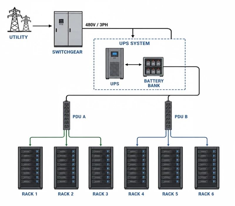
The basic power path from utility to rack
Most facilities follow a logical power sequence, even though the exact equipment varies by size, design philosophy, and redundancy requirements. Understanding this sequence helps teams read a data center power distribution diagram and make better decisions during expansion, maintenance, or troubleshooting.
A typical path includes:
Utility service or on-site generation - Power enters the site from the electric utility, with generators often used as standby or emergency sources.
Main switchgear - Large electrical equipment receives, protects, and routes incoming power to downstream systems.
Automatic transfer equipment - Transfer systems move loads between normal and backup sources when the design requires it.
Uninterruptible power supply systems - UPS equipment provides short-term backup and power conditioning for critical IT loads.
Transformers and distribution panels - These adjust voltage and divide power into smaller branch circuits.
Rack-level distribution - Remote power panels, busways, floor PDUs, or rack PDUs deliver power directly to servers and network equipment.
This chain should be reflected in the facility's electrical diagram. When diagrams are accurate, operators can identify upstream and downstream dependencies before taking equipment offline or adding new load.
Core components of electrical distribution
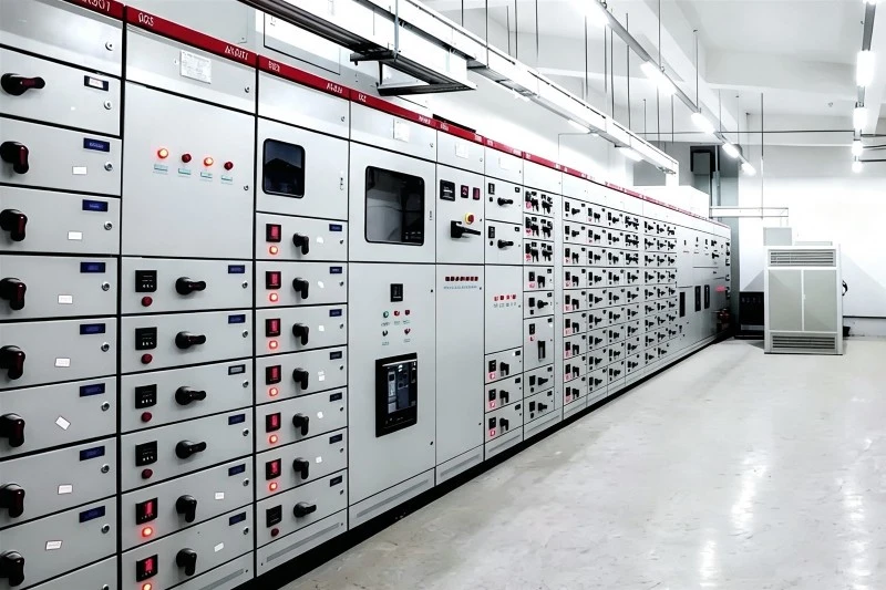
Switchgear and switchboards
Switchgear and switchboards act as major routing and protection points. They contain breakers, protective devices, metering, and controls that help isolate faults and manage large sections of the electrical distribution system. In a data center, these components are often arranged to support multiple power paths, maintenance access, and selective shutdowns.
The practical value is control. Operators can service one part of the system without unnecessarily affecting unrelated loads, provided the data center infrastructure was designed with isolation in mind.
UPS systems
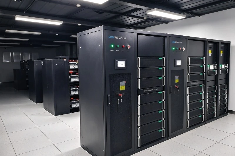
A UPS bridges the gap between a power disturbance and the availability of another stable source, such as a generator. It may also improve power quality by smoothing interruptions, voltage irregularities, or other disturbances that sensitive IT equipment may not tolerate well.
UPS design decisions affect footprint, runtime, maintenance approach, efficiency, and redundancy. For this reason, UPS capacity should be planned with both current IT load and realistic growth in mind.
PDUs, panels, and busways
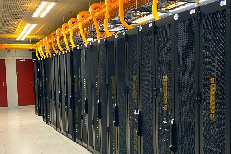
Power distribution units, panelboards, and busways divide power into usable circuits for rows, cabinets, or individual racks. A floor-mounted PDU may serve several racks, while overhead busway can make it easier to add or modify tap-off boxes as the data center layout evolves.
Rack PDUs are the final distribution point before equipment power supplies. Depending on the model, they may provide basic outlet access, metering, switching, or environmental data that feeds into a power management system.
Monitoring and controls
A power management system gathers data from meters, breakers, UPS units, generators, rack PDUs, and other devices. This visibility helps teams compare available capacity with actual demand, spot abnormal trends, and plan changes before capacity becomes a constraint.
Monitoring is most useful when it is tied to real operational decisions. For example, measured load at the rack, row, and panel level can guide where new servers should be placed and where additional electrical capacity may be required.
Why does redundancy matter in data center design?
Redundancy matters because critical equipment should not depend on a single component, cable, panel, or power source whenever the business requires high availability. A redundant design provides alternate paths so maintenance, equipment failure, or a source interruption is less likely to stop IT operations.
Redundancy can be applied in several ways. Dual utility feeds, generators, parallel UPS modules, separate A-side and B-side distribution paths, and dual-corded IT equipment all support resilience. The right approach depends on the facility's risk tolerance, budget, operating model, and uptime requirements.
Common redundancy concepts include:
Single-path distribution: Simpler and less expensive, but more vulnerable to planned or unplanned outages.
A/B power paths: Two independent paths serve dual-corded equipment, reducing dependence on one distribution chain.
Redundant UPS capacity: Extra UPS modules allow the system to support the load even if one module is unavailable.
Maintainable design: Equipment can be isolated and serviced without shutting down critical loads, if the full system supports that operating mode.
Redundancy only works when it is documented, tested, and maintained. A design that looks resilient on paper can still fail operationally if labeling is unclear, loads are unbalanced, or both equipment power cords are accidentally connected to the same path.
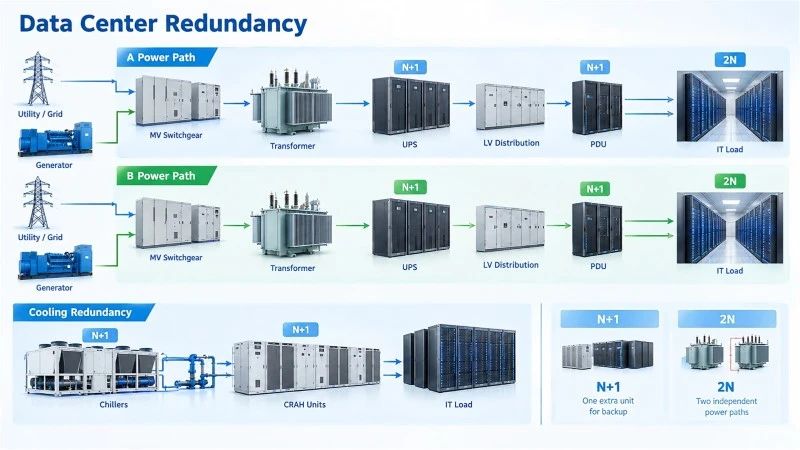
Reading a data center power distribution diagram
A data center power distribution diagram is a visual map of how power moves through the facility. It may be a one-line diagram, a detailed electrical diagram, a rack power map, or a layered drawing that connects electrical distribution to the physical data center layout.
When reviewing a diagram, look for:
Power sources: utility feeds, generators, fuel systems, and transfer points.
Major equipment: switchgear, UPS systems, transformers, panels, and PDUs.
Protective devices: breakers, fuses, relays, and disconnects.
Load relationships: which racks, rooms, cooling systems, or support loads depend on each upstream component.
Redundant paths: A-side and B-side separation, shared components, and possible single points of failure.
Capacity information: breaker ratings, transformer capacity, measured loads, and reserved capacity where shown.
The best diagrams are kept current. If field conditions change but the drawing does not, the diagram can become misleading during emergencies, maintenance windows, or expansion planning.
Power planning and data center layout
Electrical planning and physical layout should be developed together. A data center layout that ignores power can create hot spots of electrical demand, long cable runs, overloaded panels, or stranded capacity in the wrong part of the room. Conversely, a layout informed by electrical capacity can make growth more predictable.
Start by grouping loads logically. High-density racks may need different power delivery, cooling support, and monitoring than lower-density network cabinets. Critical systems may need dual power feeds, while some support loads may be acceptable on a less redundant path.
A practical planning checklist includes:
Confirm the expected IT load before assigning rack locations.
Match rack density to available branch circuit and cooling capacity.
Keep A-side and B-side distribution physically and electrically distinct where redundancy is required.
Leave access space for safe maintenance of electrical equipment.
Label panels, breakers, cables, and rack PDUs consistently.
Update drawings after every meaningful change.
Review monitoring data before approving new deployments.
This coordination reduces surprises. It also helps facilities, IT, and operations teams work from the same source of truth.
How should teams improve power management over time?
Teams should improve power management by combining accurate documentation, continuous monitoring, disciplined change control, and regular review of capacity trends. The goal is not simply to collect electrical data, but to turn that data into better operational decisions.
A useful power management system can show where load is increasing, where redundancy is at risk, and where unused capacity still exists. Over time, this supports smarter procurement, safer maintenance planning, and more efficient use of existing infrastructure.
Strong operating habits include reviewing alarms promptly, balancing loads across redundant paths, validating diagrams after changes, and training staff to understand the power path. These habits are especially important as facilities add higher-density equipment or reorganize their data center infrastructure.
Key takeaways for reliable power distribution
Reliable power distribution starts with a clear design and continues through daily operations. The major equipment matters, but so do documentation, labeling, monitoring, and coordination between teams.
Remember these essentials:
A power distribution system is an end-to-end chain from source to rack.
Redundancy must be designed, documented, tested, and maintained.
A current electrical diagram is critical for safe troubleshooting and expansion.
The physical data center layout should reflect power and cooling realities.
A power management system is most valuable when it informs real decisions.
When these pieces work together, the facility becomes easier to operate and better prepared for growth. Power distribution is not just an engineering requirement; it is one of the foundations of dependable data center infrastructure.
Q: How soon can you delivery the transformer?
A: It depends on the quantity and capacity of the transformer, normally within one month since the date drawing confirmed by buyer.
Q: How long can you provide the quality warranty?
A: 24 months since the date transformer operated.
Q: What payment method do you accept?
A: T/T (wire transfer) preferred, L/C both accepted.


