

Understanding the Basics of Electrical Transformers
An electrical transformer transfers energy between circuits through a changing magnetic field, usually to raise or lower alternating-current voltage. The electrical pole transformer above a street and the green transformer cabinet beside a driveway perform the same essential job: adapting distribution voltage for local use. Understanding their operation, components, ratings, and symbols makes neighborhood electrical equipment easier to recognize-and its hazards easier to respect.
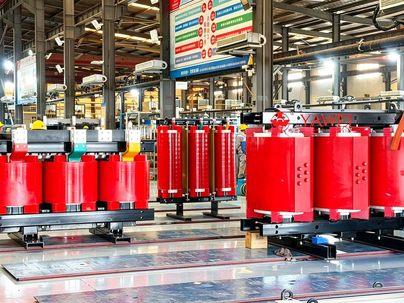
How does an electrical transformer work?
A transformer works through electromagnetic induction. Alternating voltage applied to its primary winding produces a changing magnetic field in a shared core, which induces voltage in the secondary winding. The relationship between the number of turns in the two windings determines whether the output voltage is higher or lower than the input voltage. This is the basic transformer working principle.
Picture two separate coils wrapped around a magnetic core. They do not need a direct conductive connection to transfer energy; the changing magnetic field links them. In a conventional two-winding transformer, insulation separates the windings from each other and from conductive structural parts. That separation is an important feature, but it does not make either circuit safe to touch.
The process becomes easier to follow as a sequence: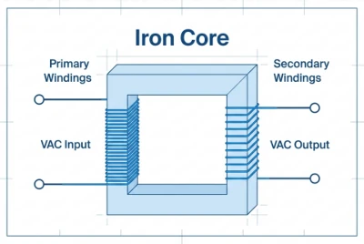
The supply energizes the primary winding. Alternating current establishes a changing magnetic field.
The core guides magnetic flux. Its magnetic properties help link the windings effectively.
The secondary develops voltage. The changing flux induces an electrical potential across its terminals.
A connected load draws current. The primary then draws additional current to supply the load, along with the transformer's losses.
Turns ratio controls the voltage change
For an ideal transformer, the voltage ratio equals the winding turns ratio:
Primary voltage ÷ secondary voltage = primary turns ÷ secondary turns
Suppose an illustrative transformer has 1,000 primary turns and 100 secondary turns. Its primary-to-secondary ratio is 10:1, so a 2,400-volt input corresponds to a 240-volt output in the ideal model. These numbers explain the relationship; they are not specifications for a particular utility installation.
More secondary turns produce a step-up transformer. Fewer secondary turns produce a step-down transformer. Equal turns can provide approximately equal input and output voltages, although isolation and other design requirements may still make the transformer useful.
Current changes in the opposite direction. Ideally, stepping voltage down by a factor of ten allows secondary current to be ten times primary current at the same transferred power. A transformer does not create extra energy: real output power is lower than input power because some energy becomes heat. The load determines the actual current drawn within the equipment's operating limits.
Alternating current is essential
Ordinary power transformers depend on changing magnetic flux, so they are designed for alternating current at specified frequencies. Steady direct current cannot sustain the normal induction process and can cause damaging current and overheating in a transformer designed for AC. Voltage alone is therefore not enough to establish compatibility; frequency and waveform also matter.
Transformers connect the stages of the power grid
Electricity travels through several voltage levels before reaching a home. Higher transmission voltage allows a given amount of power to move with less current, reducing resistive losses in conductors. Near communities, substations reduce transmission voltage to distribution levels; local distribution transformers then reduce it again for customers.
The neighborhood transformer is therefore one link in a larger chain, not a small generating station. It receives energy from upstream equipment and delivers it at a different voltage. If the supply feeding it is interrupted, it cannot independently keep nearby homes powered.
A useful way to picture the sequence is:
Generation: Electrical energy enters the grid from generating resources.
Transmission: Step-up transformers support efficient movement over longer distances.
Distribution: Substation transformers supply local distribution circuits.
Customer supply: Distribution transformers provide the voltage required by connected buildings.
This explains why the wires above a street and the wiring inside a house are not interchangeable. Each stage has its own voltage, insulation, protection, and clearance requirements. Household service voltage is suitable for equipment designed to use it, but it remains capable of causing fatal shock or fire.
The main components inside and around a transformer
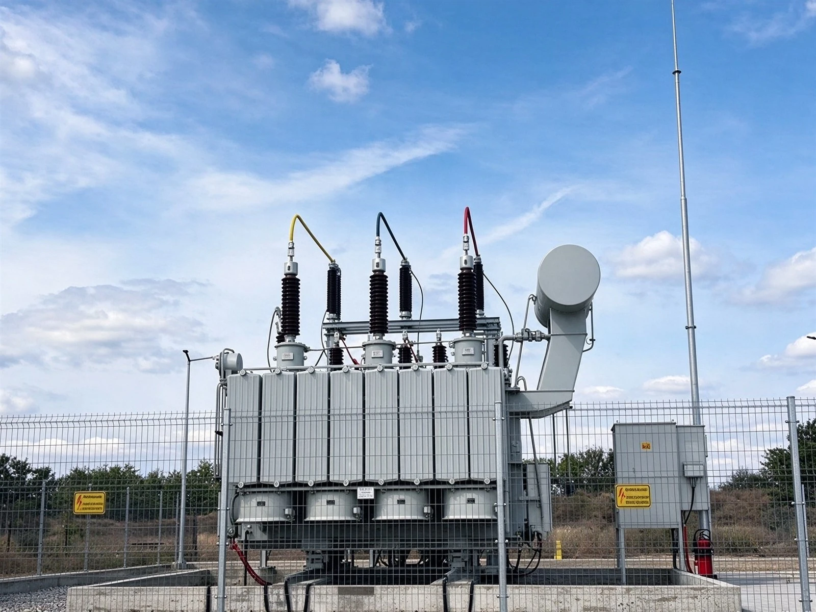
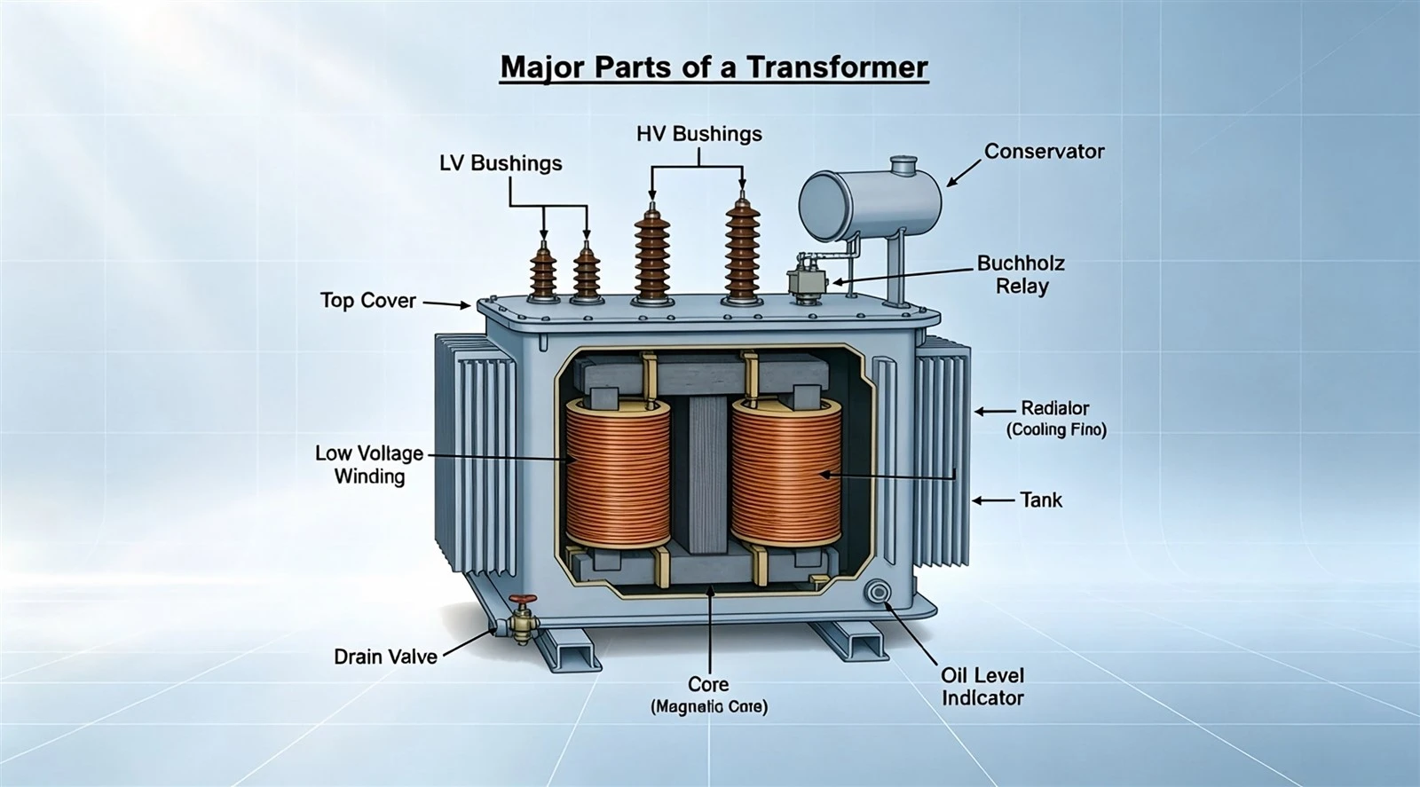
The tank or cabinet is only the visible enclosure. Inside, the core, windings, insulation, and cooling system work together; outside, terminals and protective equipment connect the transformer to the distribution network. Specific arrangements vary, so a component visible on one installation may be enclosed or absent on another.
Magnetic core and windings
The core provides a magnetic path linking the windings. Many power transformers use laminated magnetic steel, with thin insulated layers that help limit circulating eddy currents and associated heating. Core material and construction influence losses, size, and operating behavior.
The windings are insulated conductors, commonly copper or aluminum. Their turns establish the voltage relationship, while conductor dimensions and thermal design help determine current-carrying capability. Neither material alone establishes overall quality: the complete electrical and mechanical design matters.
Insulation, cooling fluid, and the tank
Insulation prevents unwanted current paths between turns, windings, and grounded metalwork. In liquid-filled transformers, insulating fluid also transfers heat away from the active components toward the tank and surrounding air. Mineral oil and alternative dielectric fluids are used in different designs.
The tank contains these components and fluid. Cooling depends on the equipment's construction, loading, and surrounding conditions-not simply whether the outside looks clean. Excessive temperature can accelerate insulation deterioration, which is one reason thermal limits are central to transformer operation.
Bushings and protective equipment
Bushings provide insulated paths for electrical connections through an enclosure. Pole-mounted units may also have pressure-relief devices, grounding provisions, and optional monitoring accessories. Some protective features are built into the transformer, while others belong to the surrounding utility installation.
Fuses and breakers interrupt certain abnormal current conditions. Surge arresters help limit transient overvoltages, while pressure-relief devices address excessive internal pressure; these devices serve different purposes. None is a substitute for proper insulation, grounding, qualified maintenance, or keeping people away from energized equipment.
What distinguishes an electrical pole transformer?
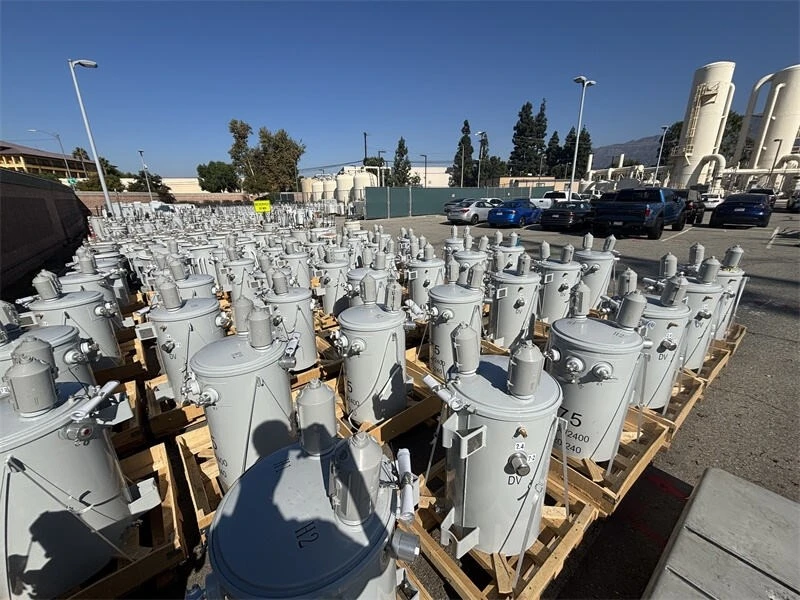
An electrical pole transformer is a distribution transformer designed for installation on a utility pole, usually serving an overhead distribution system. Residential installations commonly use single-phase units, while groups of pole-mounted transformers can supply three-phase loads. Its mounting, connections, enclosure, and capacity reflect its distribution role rather than a different operating principle.
The familiar cylindrical metal tank often sits below the main distribution conductors. Insulated bushings connect its windings to the incoming supply and outgoing secondary conductors. Although the shape is recognizable, appearance alone cannot establish its voltage, capacity, protection arrangement, or which buildings it supplies.
Pole-mounted equipment is designed around practical installation constraints. Its mounting hardware must support the unit, its insulation must suit the electrical system, and its enclosure must withstand outdoor exposure. Different units can look similar while having very different nameplate ratings, so matching a replacement by shape or tank size would be unreliable.
For a homeowner, the useful distinction is where the equipment sits in the supply path. The pole transformer performs the voltage conversion before electricity reaches the building's service equipment. It is not the household breaker panel, and its protective equipment does not replace the branch-circuit protection inside the home.
The green electrical transformer box serves underground distribution
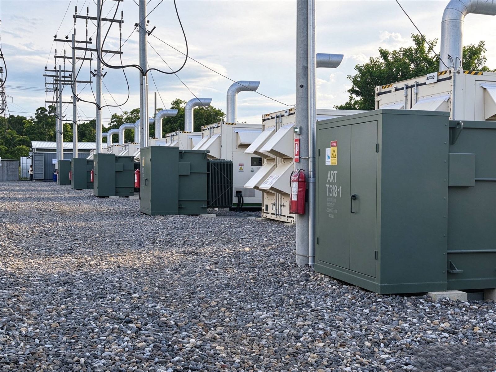
The green electrical transformer box found in many neighborhoods is commonly a pad-mounted transformer. It performs the same basic voltage-conversion function as a pole-mounted unit, but its connections serve underground cables and are enclosed in a ground-level cabinet. It typically rests on a prepared pad rather than hanging from a pole.
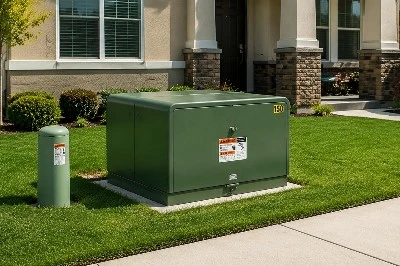
Not every green utility cabinet is a transformer. Other electrical or communications equipment can use similar enclosures, and paint color is not a reliable identification method. Treat an unfamiliar utility cabinet as equipment to leave alone rather than something to inspect by opening it.
The mounting choice changes access needs. A pole-mounted transformer requires overhead access; a pad-mounted unit requires unobstructed access to its cabinet and surrounding work area. Landscaping, fencing, stored materials, and decorative covers can interfere with utility work or conceal damage.
Before planning improvements near a cabinet:
Ask the utility for its clearance requirements. Do not assume a distance quoted for another utility applies locally.
Keep access routes and doors unobstructed. Crews may need space during an outage or replacement.
Arrange underground utility locating before digging. Cables may extend beyond the visible cabinet.
Report damaged or unsecured equipment. Never try to repair the enclosure or secure it yourself.
Transformer types describe different design choices
Transformer terminology becomes less confusing when each label is tied to a particular characteristic. "Single-phase" describes the electrical system, "pole-mounted" describes installation, and "liquid-filled" describes insulation and cooling. A single transformer can fit all three descriptions at once.
| Classification | What it describes | Practical significance |
|---|---|---|
| Step-up or step-down | Direction of voltage change | Matches supply voltage to the required output |
| Single-phase or three-phase | Electrical supply arrangement | Must suit the connected service and loads |
| Pole-mounted, pad-mounted, or substation | Installation and application | Determines enclosure, connections, and access needs |
| Liquid-filled or dry-type | Insulation and cooling approach | Affects thermal design and installation requirements |
| Distribution or instrument | Intended function | Distinguishes load supply from measurement and protection |
These categories describe different aspects of equipment selection, not competing names for the same feature. A distribution transformer supplying customers should not be confused with an instrument transformer supplying metering or protective devices.
Dry-type transformers use insulation systems without a liquid-filled tank; ventilated designs rely on airflow for cooling. Liquid-filled equipment uses dielectric fluid as part of its insulation and heat-transfer system. Neither label, by itself, establishes that a transformer is suitable for a particular indoor or outdoor location.
Core-form and shell-form describe how the magnetic structure and windings are arranged. These distinctions matter to engineers evaluating magnetic paths, mechanical behavior, and performance. They are less useful to a homeowner than the service voltage, equipment location, and utility's access requirements.
Residential supply and the meaning of 120/240 volts
In a common United States residential arrangement, a single-phase transformer has a center-tapped secondary winding. The voltage across the full winding is nominally 240 volts, while either end to the center tap provides nominally 120 volts. The center tap forms the neutral connection for this split-phase supply.
This arrangement supports both ordinary 120-volt circuits and equipment designed for 240 volts. It does not mean every home has the same service, nor that every building receives power from an identical transformer. The actual service configuration must be confirmed from utility and building documentation.
For anyone researching electrical transformer residential applications, three different ratings deserve separate attention:
Transformer capacity: How much apparent power the transformer is designed to supply under specified conditions.
Service capacity: The rating and limitations of the building's service equipment and conductors.
Branch-circuit capacity: The limitations of an individual circuit supplying appliances or outlets.
Those ratings are related, but none can safely be substituted for another. A transformer rating alone does not establish how much additional equipment a house can support; load calculations and the complete supply arrangement must be considered.
Plan significant load additions early
Adding an electric vehicle charger, electric heating, or other substantial equipment is a reason to review capacity-not a reason to assume a transformer replacement is necessary. Start with a qualified electrician's assessment of the building's demand and service. Where utility-owned equipment is involved, coordinate with the utility before finalizing installation plans.
Useful information to collect includes the new equipment's electrical rating, expected operating schedule, existing major loads, and any planned future additions. Describe whether equipment may run together rather than simply listing everything in the house. This gives the people evaluating the project a clearer picture of the demand it could create.
Reading transformer ratings without confusing their roles
A transformer nameplate brings together several independent limits. Voltage ratings describe the intended electrical relationship; kVA describes apparent-power capacity; frequency, temperature, insulation, and connection information establish additional operating conditions. A compatible voltage ratio is only the beginning of a suitable specification.
Voltage ratings and taps
Primary and secondary voltage ratings identify the intended supply and output. Some transformers include taps that change the effective winding turns ratio to compensate for supply-voltage differences. A tap is an adjustment provision, not evidence that the transformer can accept any voltage.
For example, a slightly different incoming voltage can produce a corresponding difference at the secondary. An appropriate tap setting can bring the output closer to its intended value. Selection and operation of taps must follow the equipment's design and authorized procedures; a tap handle is not a homeowner voltage control.
kVA, current, and power factor
Transformer capacity is commonly stated in kilovolt-amperes, or kVA. For a single-phase load, apparent power can be calculated as voltage multiplied by current, divided by 1,000. Thus, an illustrative 240-volt load drawing 50 amperes represents 12 kVA.
Kilowatts and kVA are not always equal. Power factor relates real power to apparent power, so selecting a transformer from a kilowatt figure alone can miss the current it must carry. Correct sizing also considers the applicable load calculation, starting demands, and operating conditions rather than simply choosing the next larger number.
Temperature rise, insulation class, and ambient conditions
Temperature rise describes heating above the surrounding ambient temperature under stated conditions. Insulation class concerns the thermal capability of the insulation system. These are connected specifications, but they are not interchangeable, and neither gives permission to operate equipment outside its installation requirements.
High ambient temperature reduces the margin available for managing operating heat. Enclosures, ventilation arrangements, loading, and the specified installation environment all affect thermal performance. A transformer suitable in one location may need a different design or operating limitation elsewhere.
Efficiency depends on losses and operating load
Transformers are efficient devices, but no real transformer transfers all input energy to the load. Its efficiency is output real power divided by input real power, expressed as a percentage. A useful comparison must state operating conditions, because efficiency changes with loading and other factors.
Two main loss categories explain much of the behavior:
Core, or no-load, losses: Present whenever the transformer is energized, even when little useful power is being delivered.
Winding, or load, losses: Associated chiefly with current flowing through winding resistance and increasing approximately with the square of load current.
This distinction explains why reducing load does not eliminate every transformer loss. It also explains why equipment selection involves the expected loading pattern, not merely maximum capacity.
For illustration, doubling current in the same resistance produces roughly four times the resistive heating. That does not mean total transformer losses always quadruple, because core losses and other effects behave differently. It does show why sustained overloads are a thermal concern rather than just an accounting issue.
Avoid relying on a universal efficiency percentage for all transformers. Size, design, load, and test conditions influence the result. For an actual purchasing or engineering comparison, request loss data and efficiency information for the relevant operating conditions instead of comparing isolated headline figures.
What does the electrical symbol for a transformer show?
The electrical symbol for a transformer represents magnetically coupled windings rather than the equipment's physical enclosure. A common schematic shows two coils facing each other, sometimes with parallel lines indicating a magnetic core. Additional connections, polarity marks, and labels explain the particular arrangement.
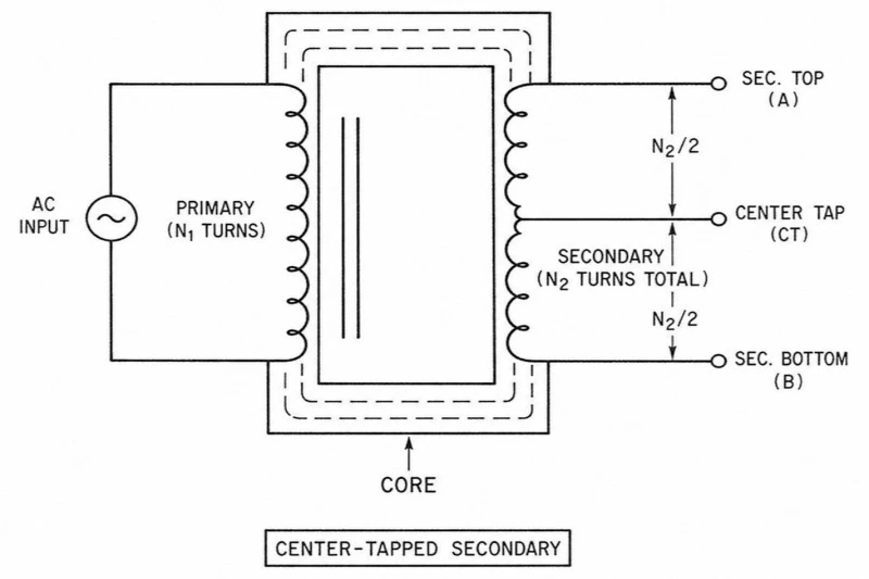
If you are searching for "transformer symbol electrical," begin with the drawing's legend. Schematic diagrams, wiring diagrams, and utility single-line diagrams serve different purposes and may represent the same transformer differently. The symbol must be read together with its labels and the rest of the drawing.
Look for these details:
Two winding representations: Identify the magnetically coupled circuits.
A secondary tap: Indicates an additional connection, such as a center tap.
Polarity dots: Show relative instantaneous polarity relationships.
Voltage and capacity labels: Provide information that the basic symbol cannot establish alone.
Polarity dots matter when windings or transformers are connected together. They are not permanent positive and negative markings like battery terminals, because AC polarity changes continuously. A simplified drawing also cannot prove that an installation is de-energized or identify every physical hazard.
Use diagrams to understand function and documented connections, not as permission to handle equipment. A homeowner reviewing a drawing can identify the transformer, follow the supply path, and note its stated ratings. Questions about actual connections or field conditions belong with qualified personnel.
Humming, maintenance, and signs worth reporting
A steady hum can be a normal result of transformer operation. Magnetostriction causes small changes in magnetic-core dimensions as the alternating field changes, producing vibration. Sound alone is therefore not proof of failure, and loudness is not a dependable measurement of transformer capacity or efficiency.
A new or markedly changed noise still deserves attention, particularly when accompanied by visible damage or other unusual conditions. Observe only from a safe location; do not approach to touch the tank, examine a terminal, or locate a leak. Report what you noticed and let the equipment owner assess it.
Professional maintenance can include inspection of connections, bushings, grounding, cooling arrangements, and insulation condition. Liquid-filled equipment may receive fluid testing where appropriate to its design and maintenance program. The scope and frequency depend on the equipment and operating context, not a universal homeowner schedule.
When making a report, describe the location and observable condition without diagnosing the cause. For example, report an open cabinet door, impact damage, smoke, or a sudden change in sound. Do not get closer to read a nameplate or take a better photograph.
Safety means keeping distance, not attempting inspection
Distribution transformers connect to hazardous electrical systems. A locked cabinet, elevated mounting position, or protective fuse does not eliminate the danger inside or around damaged equipment. Respect barriers and warning labels, and leave operation, testing, and repair to authorized personnel.
Use these practical boundaries:
Never open or climb utility equipment. Keep children from playing on or around transformer cabinets.
Keep tools and materials away from overhead lines. Ladders, poles, and equipment can create dangerous contact paths.
Stay away from fallen wires and damaged equipment. Treat lines as energized even during an outage.
Report emergencies from a safe location. Contact emergency services and the utility when fire, arcing, or fallen conductors create immediate danger.
Downed lines can energize nearby objects and surrounding areas, so avoiding direct contact with the wire is not enough. Do not move branches, fences, or other materials touching a line. Only trained utility workers should handle damaged power lines after establishing the required safety conditions.
Backup generation introduces another hazard. An improperly connected generator can send power back into utility lines, potentially energizing equipment that others expect to be disconnected. Use an approved installation designed to prevent unintended backfeeding; never improvise a connection through a household receptacle.
FAQ
Q: How soon can you delivery the transformer?
A: It depends on the quantity and capacity of the transformer, normally within one month since the date drawing confirmed by buyer.
Q: How long can you provide the quality warranty?
A: 24 months since the date transformer operated.
Q: What payment method do you accept?
A: T/T (wire transfer) preferred, L/C both accepted.


