Transformers Explained: Understanding Current Transformer Connection in Power Systems

(Click the image to learn more.)
Transformers are one of those things in power systems that usually go unnoticed-until something goes wrong. They quietly handle voltage changes so electricity can move long distances and then be safely used in homes, factories, and buildings. But alongside them, there's another device doing a different kind of job that's just as important: the current transformer. And honestly, once you start working with systems like this, the topic of current transformer connection comes up all the time.
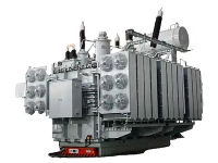
A Power Transformer is built to transfer electrical energy between voltage levels. It deals with the real power flow and is usually rated in kVA or MVA. But here's the catch-it's not designed to give safe signals for meters or protection devices. That's where the Current Transformer (CT) steps in. It takes high current and scales it down to something manageable, usually 5A or 1A, so instruments can actually read it without being damaged.
When people talk about current transformer connection, they're basically referring to how these CTs are wired into the system-especially around transformers, switchgear, and protection panels. And this wiring isn't just a detail. It directly affects how accurately the system reads current and how fast it reacts when something goes wrong.
Common Current Transformer Connection Methods

In real installations, CTs are usually placed on both sides of a power transformer. That way, engineers can see what's coming in and what's going out. If something doesn't match up, it's a red flag.
One of the most important uses of current transformer connection is in differential protection. The idea is simple: under normal conditions, current going into a transformer should match what comes out. If there's a fault inside, that balance breaks. The protection system catches it and trips the circuit almost instantly. No hesitation.
There's also a small but critical detail that people sometimes overlook-polarity. If the CT is wired the wrong way around, readings can go off completely or protection systems might not work properly. That's why terminals like P1, P2, S1, and S2 are clearly marked and must be followed carefully. No shortcuts here.
In everyday operation, proper current transformer connection makes life easier. It lets engineers monitor high currents safely, without directly exposing instruments to dangerous levels. It also helps with energy metering, load tracking, and fault detection in substations and industrial plants.
At the end of the day, power transformers move energy, but CTs and their connection methods help us actually see and control what's happening in the system. Without a solid current transformer connection, modern electrical networks would be a lot harder to manage-and a lot less safe.
FAQ
Q: What is a current transformer connection?
A: A current transformer connection refers to the way a current transformer (CT) is wired into an electrical system. It allows high currents to be safely measured and monitored by meters, relays, and protection devices.
Q: Why is current transformer connection important in transformer systems?
A: Proper current transformer connection ensures accurate current measurement, reliable fault detection, and effective protection of transformers and other electrical equipment. Incorrect connections can lead to inaccurate readings or protection failures.
Q: What are the most common types of current transformer connections?
A: The most common types include:
- Star (Wye) Connection
- Delta Connection
- Series Connection
- Differential Connection
Each type serves specific measurement and protection requirements in power systems.
Q: What happens if a current transformer is connected incorrectly?
A: An incorrect current transformer connection can cause measurement errors, relay malfunctions, false trips, or failure to detect actual faults. It may also compromise the safety and reliability of the entire electrical system