

Understanding the Basics of Electric Transformers
Electric transformers transfer electrical energy between circuits through electromagnetic induction, usually raising or lowering alternating-current (AC) voltage without changing its frequency. They help electricity travel efficiently through power networks and reach equipment at a suitable voltage. Understanding their operating principles, main types, ratings, and maintenance needs makes electrical systems easier to understand.
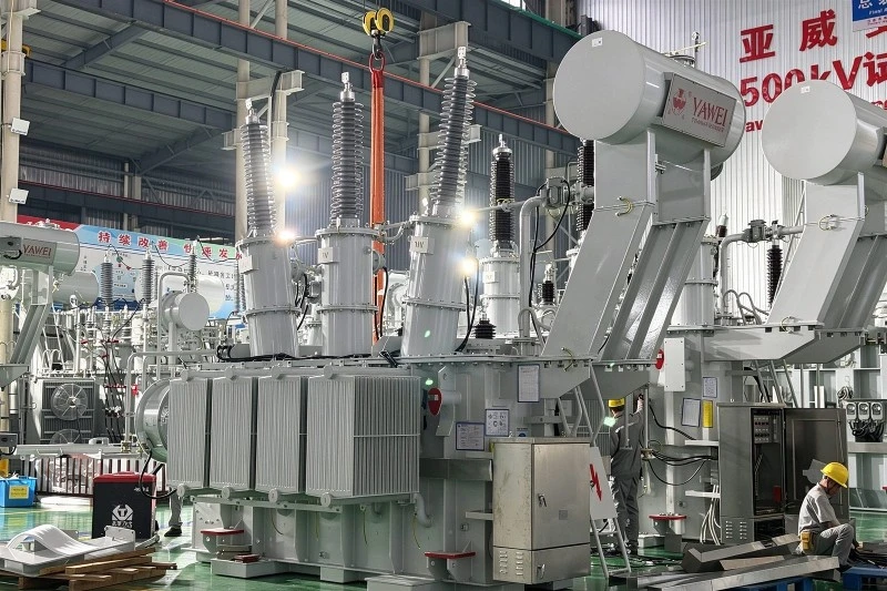
What are electric transformers used for?
Electric transformers adapt electrical supplies to the voltage requirements of a network or connected equipment. A step-up transformer increases voltage, while a step-down transformer decreases it. Some transformers instead provide electrical separation between circuits or produce proportionally reduced signals for measurement and protection. These purposes explain why transformers appear in everything from utility substations to industrial control systems.
Their importance becomes clear when following electricity from a generating station to a building. Higher transmission voltage allows power to travel with lower current for the same transferred power, reducing resistive losses in conductors. Transformers then reduce voltage through the distribution network before electricity reaches customer equipment. Without these changes, efficient long-distance delivery and practical local use would be much harder to reconcile.
A transformer does not generate electricity. It changes the relationship between voltage and current while transferring energy supplied by another source. Real units also lose some energy, mainly as heat, so their output power is lower than their input power.
How does a transformer work?
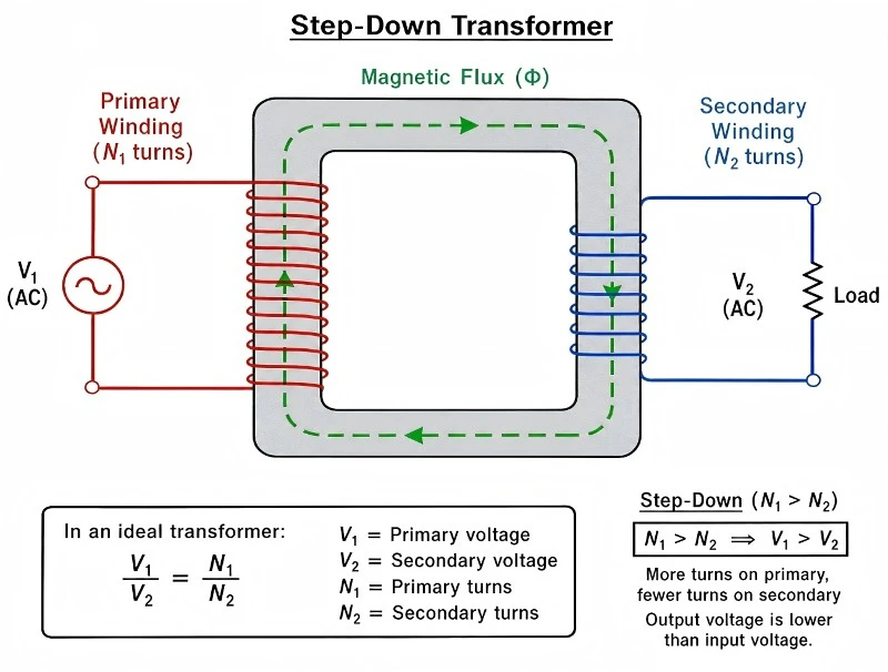
A conventional transformer works by using AC in an input winding to create a changing magnetic field. That field links with an output winding and induces a voltage in it. When a suitable load completes the output circuit, current flows to the connected equipment. The process is called mutual induction.
The input winding is called the primary, and the output winding is the secondary. In a two-winding transformer, energy passes magnetically between these windings rather than through a direct conductive connection. A magnetic core helps guide the field so that the windings couple effectively.
The turns ratio controls voltage
The voltage relationship depends mainly on the number of wire turns in each winding. In an ideal transformer, secondary voltage divided by primary voltage equals secondary turns divided by primary turns. More secondary turns produce a higher output voltage; fewer secondary turns produce a lower one.
For example, a hypothetical transformer with ten times as many primary turns as secondary turns would reduce 240 volts to approximately 24 volts. This illustrates a 10:1 step-down ratio, not a specification for a particular product. Actual output also depends on supply conditions, internal losses, and loading.
Voltage changes do not create extra power
In an ideal transformer, increasing voltage reduces the current available for the same power transfer, while decreasing voltage allows proportionally higher current. Real transformers add losses to that relationship. A higher output voltage therefore does not mean the device has created additional energy.
Conventional transformers require a changing magnetic field and cannot continuously transform steady DC directly. Electronic power converters can use transformers by switching electrical energy into a changing waveform first. The transformer itself is therefore distinct from the complete converter that surrounds it.
Main components and defining characteristics
Although construction varies, common electrical transformers contain several elements that work together to transfer energy, control temperature, and maintain insulation. Their design must handle both normal operation and the electrical stresses expected in the intended application. The basic components include:
Windings: Conductive coils, commonly copper or aluminum, that establish the input and output electrical relationships.
Magnetic core: A path for magnetic flux; laminated steel construction helps limit unwanted circulating currents and associated heating.
Insulation: Materials that separate energized parts from one another and from grounded components.
Cooling arrangements: Air, insulating liquid, and sometimes additional cooling equipment that remove operating heat.
Connections and enclosure: Terminals, bushings where applicable, and protective structures suited to the installation environment.
These components are interdependent. Sound windings alone cannot compensate for deteriorated insulation or inadequate cooling. That is why operating condition and installation environment matter alongside the voltage ratio printed on a specification sheet.
Which transformer types serve different applications?
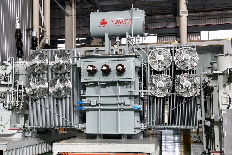
Transformer types can be classified by purpose, construction, cooling method, or electrical arrangement. These categories overlap rather than forming separate, mutually exclusive groups. A unit might simultaneously be a three-phase, liquid-filled, step-down distribution transformer. Understanding the classification behind a label is more useful than treating every label as a completely different technology.
Power, distribution, and industrial transformers
Power transformers handle energy transfer within power systems, including generation and substation applications. Distribution transformers supply downstream networks and customer loads, bringing electricity closer to its utilization voltage. Both operate through induction, but their specifications reflect their particular network duties.
The term industrial transformers describes an application setting rather than one universal design. Industrial installations may need general-purpose distribution units, control transformers, drive isolation transformers, or equipment designed for unusual environmental conditions. The important question is which electrical and environmental demands the unit must satisfy-not simply whether it carries an industrial label.
Isolation and instrument transformers
An isolation transformer uses electrically separate windings to transfer energy while separating circuits conductively. Isolation does not necessarily require a voltage change. It also does not make the secondary circuit automatically safe to touch; electrical hazards still require appropriate protective measures.
Instrument transformers serve measurement and protection rather than supplying ordinary equipment loads. Voltage transformers provide a proportionally reduced voltage signal for meters, relays, and control systems. Current transformers perform a related function for current measurement, so the two should not be confused when reading drawings or equipment descriptions.
Dry-type and liquid-filled construction
Dry-type transformers use solid insulation systems and air-based cooling rather than liquid immersion. Ventilated designs depend on unobstructed airflow, making installation clearances and cleanliness important. Liquid-filled transformers use insulating fluid that also carries heat away from internal components.
Neither construction is automatically best for every location. Selection must account for the installation environment, cooling arrangements, access, and applicable project requirements. Indoor and outdoor suitability depends on the complete design and enclosure, not just the cooling category.
Reading transformer ratings and specifications
A transformer's nameplate summarizes operating conditions that must match the application. Start with input and output voltage, but do not stop there. Frequency, phase arrangement, capacity, and thermal characteristics can determine whether an apparently suitable unit is actually appropriate.
Use this checklist when reviewing specifications:
Primary and secondary voltage: Confirm the available supply and the voltage required by the load.
Capacity in VA, kVA, or MVA: Check the apparent-power rating, not just the equipment's stated watts.
Single-phase or three-phase configuration: Match the supply, load, and required winding connections.
Frequency: Verify compatibility with the intended electrical system.
Temperature rise and insulation information: Evaluate the thermal design alongside expected operating conditions.
Impedance: Recognize its effect on voltage drop and available short-circuit current.
Tap settings: Identify available adjustments for accommodating specified supply-voltage differences.
A kilovolt-ampere rating is not interchangeable with a kilowatt rating in every application. Power factor affects the relationship between apparent power and real power. Load characteristics, motor starting, and nonlinear equipment may also require additional evaluation rather than simple nameplate addition.
Transformer taps deserve particular care. They change the effective winding ratio, but adjustment procedures depend on the equipment design. Do not assume a tap can be changed while energized; the manufacturer's instructions and qualified personnel must determine the correct procedure.
Practical examples across electrical systems
The same operating principle supports very different jobs. Consider these examples when connecting transformer terminology to an actual system:
Utility transmission: A generating-station transformer raises voltage for efficient delivery over long distances.
Local distribution: A distribution transformer lowers network voltage before supplying homes or businesses.
Commercial buildings: A general-purpose transformer adapts an available supply to lighting, receptacle, or other equipment requirements.
Industrial drives: A drive isolation transformer provides an application-specific interface between the supply and motor-drive equipment.
Substation monitoring: Instrument transformers provide scaled signals that metering and protective systems can use.
These examples also show why transformer selection begins with the task. A unit intended to supply building loads is not interchangeable with an instrument voltage transformer. Similar terminology does not establish equivalent capacity, insulation, accuracy, or application suitability.
Transformer maintenance and warning signs
Transformer maintenance aims to identify deteriorating conditions before they interrupt service or create hazards. Requirements differ between dry-type and liquid-filled equipment, and inspection schedules should follow manufacturer guidance and the site's maintenance program. A generic calendar alone cannot account for every operating environment or transformer design.
For dry-type equipment, attention commonly centers on ventilation, contamination, insulation condition, and connections. For liquid-filled units, inspection may also cover fluid levels, leakage, bushings, temperature indications, and fitted monitoring devices. Specialist testing can include turns-ratio, winding-resistance, insulation-resistance, and fluid-related assessments where appropriate.
Useful observations to report include:
Blocked ventilation or heavy contamination: These conditions warrant evaluation because cooling and insulation performance matter.
Liquid leakage or an abnormal level: Follow the equipment manufacturer's response procedure rather than topping up fluid casually.
Unexpected temperature indications: Investigate the cause instead of assuming heat is simply normal operation.
Damaged or contaminated bushings: Have qualified personnel assess their condition and the required corrective work.
Treat these observations as reasons for professional assessment, not instructions to open equipment. Electrical work requires appropriate isolation, lockout/tagout practices, and verification of de-energization by qualified personnel. Turning off a switch is not, by itself, proof that exposed parts are safe.
The essential takeaway
Electric transformers make electrical energy usable across different voltage levels and applications. Their basic principle is consistent, but their construction, capacity, insulation, and operating requirements vary considerably. Understanding the difference between voltage conversion, isolation, and measurement helps you interpret specifications without confusing one duty for another.
For any real installation, combine that understanding with the correct nameplate information, manufacturer documentation, and qualified electrical support. Good selection and transformer maintenance depend on the complete system-not on voltage ratio alone.
FAQ
Q: How soon can you delivery the transformer?
A: It depends on the quantity and capacity of the transformer, normally within one month since the date drawing confirmed by buyer.
Q: How long can you provide the quality warranty?
A: 24 months since the date transformer operated.
Q: What payment method do you accept?
A: T/T (wire transfer) preferred, L/C both accepted.


