

Understanding Transformer Impedance, Its Calculation and Applications
Transformer impedance is an important electrical parameter that affects voltage regulation, short-circuit current, power system stability, and the overall performance of electrical distribution networks. When engineers evaluate a power transformer or distribution transformer, impedance is one of the key specifications to consider alongside rated voltage, capacity, and load requirements.
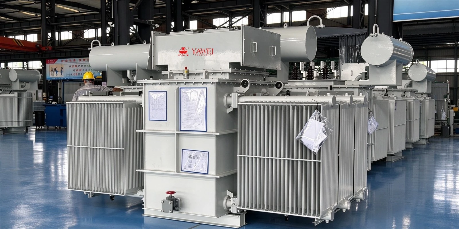
What Is Transformer Impedance?
Transformer impedance describes the opposition a transformer presents to alternating current under specified operating conditions. It includes resistance from the windings and reactance associated with magnetic flux leakage.
In practical applications, transformer impedance is commonly expressed as a percentage of rated voltage, known as percentage impedance or percent impedance (%Z). This value is generally determined through a short-circuit test according to the applicable testing standard.
For example, a transformer with a rated capacity of 1,000 kVA and an impedance of 6% has a percentage impedance of 6%. This does not mean that the transformer continuously loses 6% of its power. Instead, the impedance value describes the voltage required to circulate rated current under the specified short-circuit test conditions.
Transformer impedance is particularly important when determining fault current levels, evaluating voltage drop under load, and coordinating protective devices.
Why Is Transformer Impedance Important?
Transformer impedance influences several aspects of electrical system design and operation.
Short-Circuit Current Limitation
When a short circuit occurs on the secondary side of a transformer, the available fault current depends partly on the transformer's impedance. For a given transformer rating and voltage, a higher impedance generally results in a lower prospective short-circuit current.
This relationship matters when selecting circuit breakers, fuses, switchgear, busbars, and other electrical equipment. If the available fault current exceeds the interrupting or withstand rating of the equipment, the system may require a different transformer specification or additional current-limiting measures.
Voltage Regulation
Transformer impedance also affects voltage drop when the load increases. Under normal operating conditions, current flowing through winding resistance and leakage reactance produces a voltage drop between the no-load and loaded conditions.
A transformer with lower impedance generally experiences less voltage drop for a comparable load and power factor. However, actual voltage regulation also depends on the transformer's resistance-to-reactance ratio, loading level, and whether the load is inductive or capacitive.
For facilities with sensitive electrical equipment, stable voltage is especially important. Data centers, manufacturing plants, hospitals, and commercial buildings must consider impedance when designing reliable power distribution systems.
Parallel Transformer Operation
When two or more transformers operate in parallel, their voltage ratios, phase relationships, vector groups, and impedances must be compatible. Their impedance values should be sufficiently close, when expressed on a common rating basis, to support appropriate load sharing.
If parallel transformers have significantly different impedances, they may not share the load proportionally to their rated capacities. One unit could become overloaded while another remains underutilized.
Proper transformer selection and engineering verification can help prevent these problems.
How Is Transformer Impedance Calculated?
Transformer impedance can be expressed in percentage form, per-unit form, or as an equivalent impedance in ohms.
The basic percentage impedance formula is:
Percentage impedance = (Short-circuit test voltage / Rated voltage) × 100%
During a standard short-circuit test, one winding is typically short-circuited while a reduced voltage is applied to the other winding. The voltage required to produce the specified test current is measured and used to determine the impedance.
For example, if 6% of the rated voltage is required to circulate rated current during the specified test, the transformer's percentage impedance is 6%.
For a three-phase transformer, the approximate rated line current can be calculated using:
Rated current = Rated apparent power / (√3 × Rated line voltage)
These calculations help engineers assess transformer loading and estimate fault current.
For a simplified example, consider a 1,000 kVA transformer with a rated secondary voltage of 400 V and an impedance of 6%.
The rated secondary current is approximately:
1,000,000 / (√3 × 400) ≈ 1,443 A
Assuming an idealized, bolted three-phase fault at the transformer terminals, with an adequately stiff upstream supply and no other significant impedance, the initial symmetrical fault current is approximately:
1,443 / 0.06 ≈ 24,050 A
The estimated value is about 24 kA. In a real installation, upstream source impedance, cables, busbars, and other system characteristics will affect the actual fault current. Detailed short-circuit calculations should therefore be completed before selecting protective equipment.
What Factors Affect Transformer Impedance?
Several design and manufacturing factors influence transformer impedance.
Winding design: The arrangement, dimensions, and spacing of high-voltage  and low-voltage windings affect leakage flux and therefore leakage reactance.
Transformer capacity: Larger transformers often have different impedance requirements because of their voltage levels, current ratings, physical dimensions, and intended applications. Capacity alone, however, does not determine the impedance value.
Voltage rating: High-voltage power transformers and medium-voltage distribution transformers may require different impedance specifications according to their operating conditions and system requirements.
Manufacturing tolerances: Winding geometry, conductor positioning, and dimensional accuracy affect the final impedance. Manufacturing quality control helps ensure that measured results meet the approved design requirements.
Customer specifications: Utilities, industrial plants, renewable energy projects, and data center operators may specify particular impedance values to coordinate with existing equipment and fault-level limits.
Transformer impedance should therefore be selected through engineering evaluation rather than simply choosing the lowest available percentage.
Typical Transformer Impedance Values
There is no single impedance value suitable for every transformer. The appropriate specification depends on rated capacity, voltage class, applicable standards, system fault levels, and project requirements.
For preliminary engineering discussions, the following ranges may be useful as broad examples rather than mandatory design limits.
| Transformer application | Illustrative impedance range |
|---|---|
| Small distribution transformers | 2%–6% |
| Medium-capacity distribution transformers | 4%–8% |
| Larger industrial power transformers | 6%–12% |
| Specialized high-capacity power transformers | Project-specific |
Actual values vary considerably, particularly for large power transformers and units designed for specialized applications. Engineers should refer to the manufacturer's guaranteed technical data, applicable standards, and utility requirements when confirming a specification.
How to Choose the Right Transformer Impedance
Selecting transformer impedance requires a balance between operational performance and system protection.
First, determine the maximum allowable short-circuit current at the installation point. The transformer impedance must be evaluated together with the upstream grid fault level and the ratings of downstream equipment.
Next, assess voltage regulation under normal and peak loading conditions. Facilities with large motors, variable-frequency drives, rectifiers, or other nonlinear loads may need additional power-quality analysis.
For parallel operation, compare impedance values on a common reference basis and verify voltage ratios, vector groups, polarity, and phase sequence. Load-sharing calculations should confirm that each transformer can operate within its rated limits.
Finally, consider future expansion. A transformer that meets today's load requirements may become unsuitable if a facility adds production lines, EV charging infrastructure, renewable energy equipment, or additional data center capacity.
A qualified electrical engineer should verify the complete design before the transformer is ordered or installed.
Transformer Impedance in Power Distribution Projects
Transformer impedance is relevant to a wide range of applications, including industrial facilities, commercial buildings, utility substations, renewable energy plants, and data centers.
In industrial systems, the correct impedance helps balance voltage performance  and fault-current limitations. In data centers, it forms part of the electrical coordination process involving medium-voltage switchgear, main transformers, low-voltage distribution equipment, UPS systems, and downstream loads.
For solar and wind projects, transformer impedance must also be considered alongside inverter characteristics, grid interconnection requirements, and the overall system fault analysis.
For utility applications, engineers may need to coordinate impedance across several voltage levels to achieve the required protection and operating performance.
In every case, the transformer should be selected according to the electrical characteristics of the complete system, not only its rated power.
Choose a Transformer Manufacturer That Understands Your Requirements
Jiangsu Yawei Transformer Co., Ltd., a subsidiary of Yawei Group, was established in 1993 and has more than 30 years of transformer manufacturing experience. The company serves power distribution, industrial, and energy infrastructure applications with a range of transformer products and customized solutions.
When specifying a transformer, customers should provide the rated capacity, primary and secondary voltages, frequency, vector group, required impedance, cooling method, installation environment, and applicable standards. Additional information about upstream fault levels and parallel operation can help the engineering team evaluate the design more accurately.
Yawei Transformer supports project-specific transformer requirements, helping customers identify suitable technical specifications for their electrical systems.
Looking for a transformer with a specific impedance requirement? Contact Yawei Transformer to discuss your project, request a quotation, and obtain technical information for your application.
FAQ
Q: How soon can you delivery the transformer?
A: It depends on the quantity and capacity of the transformer, normally within one month since the date drawing confirmed by buyer.
Q: How long can you provide the quality warranty?
A: 24 months since the date transformer operated.
Q: What payment method do you accept?
A: T/T (wire transfer) preferred, L/C both accepted.


