What Is Inside a Power Transformer? Understanding Transformer Parts and Components
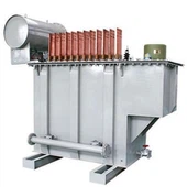
At first glance, a power transformer may look like a large steel box sitting in a substation or industrial facility. But inside that enclosure is a carefully designed system made up of electrical, magnetic, mechanical, and protection components - all working together to transfer electrical energy safely and efficiently.
Many people only see the outside of a transformer, but the real engineering work happens inside. The transformer parts, from the magnetic core to the windings, insulation materials, and cooling equipment, each have an important role. If even one component is poorly designed or maintained, transformer performance and reliability can be affected.

This guide takes a closer look at the components of power transformer, explaining the power transformer structure, the basic components of power transformer, and the accessories used to keep transformers operating safely for decades.
Understanding the Structure Inside a Power Transformer
A power transformer is built around several major systems. While transformer designs vary depending on voltage level, capacity, and application, the internal structure is generally based on the same principle: create a magnetic field, transfer energy, control heat, and protect the equipment.
The main sections include:
| System | Main Components | Function |
|---|---|---|
| Magnetic system | Core, core clamps, magnetic steel laminations | Provides a path for magnetic flux |
| Electrical system | HV winding, LV winding, leads | Transfers electrical energy |
| Insulation system | Transformer oil, paper insulation, pressboard | Prevents electrical breakdown |
| Cooling system | Radiators, fans, oil circulation equipment | Removes heat generated during operation |
| Protection system | Relays, sensors, pressure devices | Detects and prevents faults |
The transformer assembly brings all these systems together into one complete unit. It is not just about connecting parts - the spacing, insulation, and mechanical strength all need to be carefully calculated.
Magnetic Components Power Transformer: The Core of Energy Transfer
The magnetic system is one of the most important parts inside any transformer. Without it, electromagnetic energy transfer simply cannot happen.
The main magnetic components power transformer  uses are the iron core and its supporting structures.
The core is usually manufactured from grain-oriented silicon steel sheets. These sheets are stacked together to reduce energy losses caused by eddy currents.
A transformer core mainly contains:
Core limbs, where the windings are installed
Yokes, which connect the limbs and complete the magnetic path
Clamping structures, which hold the core firmly in place
Modern transformer cores often use step-lap technology to improve efficiency and reduce noise.
| Core Component | Material | Purpose |
| Silicon steel laminations | Grain-oriented electrical steel | Reduces core losses |
| Step-lap joints | Laminated steel structure | Improves magnetic performance |
| Core clamps | Steel support structure | Keeps the core assembly stable |
| Insulating coating | Electrical insulation material | Reduces circulating currents |
The core may seem like a simple stack of steel sheets, but its design has a major impact on transformer efficiency.
Transformer Windings: Where Electrical Energy Flows
Among all transformer components, windings are  some of the most critical. They are responsible for receiving electrical energy, creating magnetic flux, and producing the output voltage.
A typical power transformer contains:
High-voltage (HV) winding
Low-voltage (LV) winding
Optional tertiary winding
Copper is commonly used because it offers excellent conductivity and mechanical strength. Aluminum is also used in some transformer designs where weight and cost considerations are important.
| Winding Type | Location | Main Function |
| HV winding | Designed for high-voltage operation | Handles higher voltage levels |
| LV winding | Usually closer to the core | Carries higher current |
| Tertiary winding | Additional winding | Provides system support and auxiliary functions |
A winding assembly is not only a coil of wire. It also includes insulation layers, spacers, cylinders, and supporting parts that help the transformer withstand electrical stress and short-circuit forces.
Insulation System Inside a Power Transformer
The insulation system is what keeps different electrical parts separated an d prevents dangerous internal failures.
In oil-immersed transformers, transformer oil plays a double role:
Providing electrical insulation
Carrying heat away from the active parts
The insulation system normally includes:
| Insulation Component | Function |
| Transformer oil | Provides insulation and cooling |
| Kraft paper | Wraps and insulates winding conductors |
| Pressboard barriers | Separates high-voltage sections |
| Insulating cylinders | Supports and isolates winding structures |
Over time, insulation aging is one of the main factors affecting transformer life. That is why oil testing and insulation monitoring are important parts of transformer maintenance.
Transformer Tank and Mechanical Hardware
The transformer tank is the main enclosure that protects the  internal assembly. It contains the oil and provides mechanical protection for the active parts.
Although the tank is not part of the electrical circuit, it is still an essential part of the overall transformer hardware.
Important mechanical components include:
| Hardware Component | Function |
| Main tank | Holds oil and internal components |
| Tank cover | Provides access and sealing |
| Lifting lugs | Used during transportation and installation |
| Grounding terminals | Provides safe grounding connection |
| Clamping structures | Keeps internal parts secure |
Inside a transformer, mechanical strength matters a lot. During short circuits, extremely high forces can act on the windings, so the assembly must be strong enough to handle these conditions.
Cooling Components Inside a Transformer
A transformer naturally produces heat while operating. Copper losses and core losses increase temperature, and without proper cooling, insulation can deteriorate much faster.
The cooling system usually includes:
| Cooling Component | Function |
| Radiators | Increase heat dissipation area |
| Cooling fans | Improve air movement |
| Oil pumps | Force oil circulation |
| Oil channels | Guide oil flow through hot areas |

Common transformer cooling methods include:
ONAN (Oil Natural Air Natural)
ONAF (Oil Natural Air Forced)
OFAF (Oil Forced Air Forced)
The cooling design depends on transformer size, load requirements, and installation environment.
Transformer Accessories and Protection Devices
A power transformer needs more than just a core and windings. It also requires various transformer accessories to monitor operation and protect against abnormal conditions.
Some common accessories include:
| Transformer Accessory | Function |
| Buchholz relay | Detects internal faults and gas buildup |
| Conservator tank | Allows oil expansion and contraction |
| Silica gel breather | Prevents moisture entering the transformer |
| Oil level indicator | Shows oil level condition |
| Temperature indicator | Monitors operating temperature |
| Pressure relief device | Releases excessive internal pressure |
These accessories may look small compared with the transformer itself, but they play a major role in preventing failures.


Tap Changer Assembly
Voltage levels in power systems are not always constant. A tap changer  allows transformers to adjust their turns ratio and maintain stable output voltage.
There are two main types:
Off-circuit tap changer:
The transformer must be disconnected before adjustment.
On-load tap changer (OLTC):
The transformer can adjust voltage while operating.
An OLTC assembly usually contains:
| OLTC Component | Function |
| Tap selector | Selects different winding taps |
| Diverter switch | Transfers current between taps |
| Transition resistor | Limits switching current |
| Motor drive mechanism | Controls tap movement |
| Control cabinet | Provides operation and monitoring |
Bushings and Connection Parts
Bushings are the connection points between the internal windings and external power cables. They allow electricity to enter and leave the transformer while maintaining insulation.
Typical bushing components include:
Conductive terminals
Insulation layers
Porcelain or composite housing
Mounting structures
High-voltage transformers often use advanced bushing designs such as oil-impregnated paper (OIP) or resin-impregnated paper (RIP) bushings.
Components in an Amplifier Power Transformer
Although industrial power transformers are much larger, amplifier transformers work on the same electromagnetic principle.
The components in an amplifier power transformer usually include:
| Component | Function |
| Laminated iron core | Creates the magnetic field |
| Primary winding | Receives AC input |
| Secondary winding | Provides output voltage |
| Insulation layers | Prevent electrical faults |
| Bobbin/frame | Supports the winding structure |
The components in a amplivier power transformer are simpler compared with utility transformers, but the basic idea is the same: magnetic energy transfer between windings.
How Transformer Assembly Brings Everything Together
The transformer assembly process combines all internal and external  parts into a reliable electrical machine.
Typical manufacturing steps include:
Core stacking and inspection
Winding production
Insulation installation
Core and coil assembly
Tank installation
Vacuum oil filling
Accessory installation
Electrical testing
Every step matters. A transformer may operate for 30 years or more, so manufacturing quality directly affects its service life.
Conclu sion
A power transformer contains much more than a core and a few coils. Inside are carefully designed transformer parts, including magnetic components, windings, insulation systems, cooling equipment, protection devices, and mechanical structures.
Understanding the components of a power transformer helps engineers, technicians, and buyers better evaluate transformer design and reliability.
Whether it is a large utility transformer serving a transmission network or a small amplifier transformer used in electronic equipment, the working principle remains the same: magnetic components, electrical windings, insulation, and supporting hardware work together to transfer energy safely and efficiently.
Q: How soon can you delivery the transformer?
A: It depends on the quantity and capacity of the transformer, normally within one month since the date drawing confirmed by buyer.
Q: How long can you provide the quality warranty?
A: 24 months since the date transformer operated.
Q: What payment method do you accept?
A: T/T (wire transfer) preferred, L/C both accepted.