

Electrical Substation: Complete Guide to Components, Types, Design and Applications
An electrical substation is one of those parts of the power system that most people rarely notice, but almost every reliable power network depends on it. Electricity has to travel through different voltage levels before it reaches homes, factories, commercial buildings, data centers, or renewable energy projects. Substations make that possible.
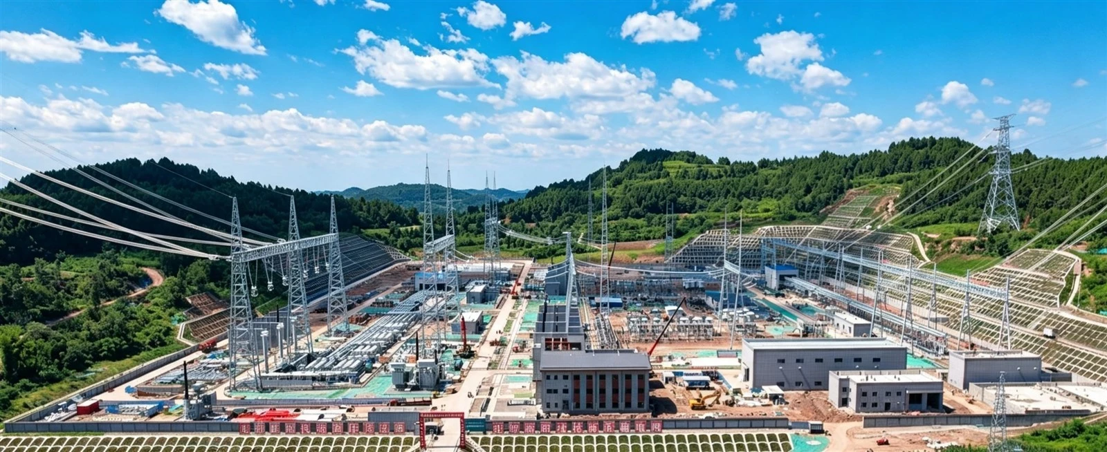
Depending on the application, an electrical substation can transform voltage, switch circuits, protect equipment, monitor electrical conditions, and control how power moves through the grid. In a large transmission network, a substation may cover a huge area and contain high-voltage power transformers, circuit breakers, busbars, protection systems, and other equipment. A smaller distribution substation may be much more compact.
For utilities, EPC contractors, industrial facilities, renewable energy developers, and other power projects, substation design is rarely about one piece of equipment. The transformer, switchgear, protection system, grounding system, and control equipment all have to work together.
What Is an Electrical Substation?
An electrical substation is a facility where electricity is transformed, switched, controlled, protected, or distributed.
The basic idea is fairly simple. Electricity generated at a power plant usually needs to be raised to a higher voltage before it can travel long distances. A transformer at a generating station increases the voltage, reducing current and therefore helping limit transmission losses.
As electricity gets closer to the end user, substations gradually reduce the voltage to levels that are suitable for regional distribution and final consumption.
A typical power path looks something like this:
Power Generation → Step-Up Transformer → Transmission Substation → Distribution Substation → Consumers
The actual voltage levels vary from one grid to another. Transmission substations may operate at 110 kV, 220 kV, 330 kV, 500 kV, 765 kV, or higher. Distribution networks often use medium-voltage levels such as 10 kV, 11 kV, 20 kV, or 35 kV.
So, while voltage transformation is a major part of what a substation does, it is certainly not the whole story.
What Does an Electrical Substation Do?
An electrical substation has several jobs, and they are closely connected.
| Function | Description |
|---|---|
| Voltage transformation | Raises or lowers voltage for transmission and distribution |
| Switching | Connects or disconnects circuits and equipment |
| Protection | Detects faults and isolates damaged sections |
| Control and monitoring | Measures electrical parameters and manages power flow |
In other words, an electrical substation is not simply a place where a transformer is installed. It is an important control and protection point within the power grid.
Main Components of an Electrical Substation
The equipment inside a substation depends on its voltage level, capacity, location, and purpose. Still, several major components are common across many installations.
The power transformer is usually one of the largest pieces of equipment in a  substation.
Its main job is to change voltage from one level to another while transferring electrical power efficiently. A transmission substation, for example, might reduce 220 kV to 110 kV, while a distribution substation could reduce medium voltage to a lower utilization voltage.
Large oil-immersed transformers are widely used for high-capacity substations because they can handle large power ratings and provide effective cooling.
Depending on the project, a transformer may include an on-load tap changer (OLTC), off-circuit tap changer, ONAN or ONAF cooling, Buchholz relay, pressure relief device, oil and winding temperature indicators, conservator tank, and online monitoring equipment.
Renewable energy projects have their own requirements. Solar farms, wind farms, and battery energy storage systems may use generator step-up transformers, collector transformers, or specially designed transformers for grid connection.
A circuit breaker carries current during normal operation and interrupts the circuit when necessary.
If a fault occurs, the protection relay detects the abnormal condition and sends a trip signal to the circuit breaker. The breaker then opens the circuit and helps prevent the fault from spreading.
High-voltage substations may use SF₆ circuit breakers or newer technologies designed with lower environmental impact. Vacuum circuit breakers are common in medium-voltage applications.
The right choice depends on voltage level, fault current, interrupting capacity, operating conditions, and project requirements.
Disconnectors, often called isolators, are mainly used to provide electrical isolation during maintenance.
They are not normally intended to interrupt large fault currents. Instead, they are operated after the relevant circuit has been de-energized, allowing maintenance personnel to work on equipment with a clear physical isolation point.
This is an important distinction: circuit breakers interrupt current, while disconnectors provide isolation.
Busbars are conductive connections that link incoming and outgoing circuits within the substation.
Different projects may use single busbar, double busbar, ring bus, breaker-and-a-half, or other arrangements. There is no single configuration that works best everywhere.
The busbar arrangement affects reliability, maintenance flexibility, fault isolation, and project cost. Critical substations may use more complicated arrangements because they provide greater flexibility during maintenance or equipment failures.
A current transformer (CT) converts a high primary current into a lower, standardized secondary current that can be safely measured by protection and metering equipment.
CTs are commonly used for overcurrent protection, earth-fault protection, differential protection, energy metering, and general power monitoring.
Getting the CT ratio and accuracy right is important. Protection CTs, in particular, need to perform properly during high fault currents, so accuracy class, burden, saturation characteristics, and protection requirements all need to be considered.
Voltage transformers (VTs), also known as potential transformers (PTs), reduce high system voltages to safer levels for measurement and protection.
They provide voltage signals to meters, relays, control equipment, and monitoring systems without directly connecting these low-voltage circuits to the high-voltage system.
Power systems can experience transient overvoltages caused by lightning strikes and switching operations.
Surge arresters help protect transformers, switchgear, cables, and other equipment by limiting these voltage surges and providing a path for surge energy to ground.
Their selection depends on system voltage, grounding conditions, temporary overvoltage, and insulation coordination. It is a relatively small component compared with a power transformer, but its role is certainly not minor.
Protection relays are essentially the decision-making part of the substation protection system.
They monitor current, voltage, frequency, phase relationships, and other electrical parameters. When they identify an abnormal condition, they can send a trip signal to the relevant circuit breaker.
Common protection functions include overcurrent, earth fault, differential, overvoltage, undervoltage, overfrequency, underfrequency, and distance protection.
Modern numerical relays can combine several protection functions with measurement, event recording, communication, and remote monitoring. This has made substation protection systems considerably more capable than older electromechanical designs.
A reliable grounding system is essential for both equipment protection and personnel safety.
The grounding system provides a controlled path for fault current and helps keep touch and step voltages within acceptable limits. A typical substation grounding grid uses buried conductors and grounding electrodes connected to transformer tanks, equipment frames, steel structures, and other conductive parts.
Grounding design depends on factors such as soil resistivity, available fault current, fault-clearing time, grid dimensions, and applicable safety requirements.
Types of Electrical Substations
There are several ways to classify an electrical substation. The most common approaches are based on its function, voltage level, installation environment, or application.
A step-up substation increases the voltage produced by a generating facility to a higher transmission voltage.
A generator may produce electricity at a relatively low voltage compared with the transmission network. The generator step-up transformer raises that voltage before electricity enters the transmission system.
Higher transmission voltage means lower current for the same power level, which helps reduce losses in transmission lines.
A step-down substation does the opposite.
It reduces a high transmission voltage to a lower voltage for regional or local distribution. For example, a 220 kV transmission line may feed a substation where the voltage is reduced to 110 kV or 35 kV.
From there, additional distribution equipment can reduce the voltage further before electricity reaches consumers.
A distribution substation is generally located closer to the electrical load.
It reduces medium-voltage power to a lower distribution voltage and supplies several outgoing circuits. Distribution substations can serve residential communities, commercial developments, factories, infrastructure projects, and other loads.
Their design is often more compact than that of a major transmission substation, although the required capacity can still be substantial.
A switching substation mainly performs switching and protection functions rather than major voltage transformation.
It can connect different transmission or distribution circuits, divide a network into sections, and improve operational flexibility. In some locations, switching substations are used to improve reliability without installing large power transformers.
An industrial substation supplies electricity to large industrial facilities such as factories, mines, steel plants, chemical plants, and processing facilities.
These projects often have demanding requirements for reliability and power quality. High starting currents, large motors, harmonics, sensitive equipment, and continuous production processes can all influence substation design.
Data centers are another good example. Their electrical systems may require redundant transformers, high-quality protection, harmonic management, and carefully coordinated backup power systems.
Large solar photovoltaic plants, wind farms, and battery energy storage systems generally require dedicated electrical infrastructure for grid connection.
A renewable energy substation may include collector transformers, medium-voltage switchgear, power transformers, protection systems, metering, reactive power compensation, and grid connection equipment.
The transformer design needs to account for the project's generation profile, grid-code requirements, harmonics, ambient conditions, and operating conditions.
Indoor vs Outdoor Substations
Substations can also be classified according to where the equipment is installed.
Outdoor substations are widely used for medium- and high-voltage applications.
Major equipment is installed outdoors on concrete foundations or steel structures. This arrangement provides enough room for large transformers, circuit breakers, busbars, and high-voltage connections.
Outdoor substations are often a practical choice for large transmission and distribution projects, especially where sufficient land is available.
Indoor Substation
In an indoor substation, major equipment is installed inside a dedicated building or enclosure.
This approach can be useful when land is limited or when equipment needs additional protection from dust, moisture, pollution, or unauthorized access.
Urban substations, industrial facilities, and projects with strict space constraints may use indoor switchgear and dry-type transformers to create a more compact installation.
AIS vs GIS Substations
High-voltage substations are commonly divided into air-insulated substations (AIS) and gas-insulated substations (GIS).
AIS uses atmospheric air as the main insulation medium between energized components. It generally requires more space, but the equipment is relatively accessible for visual inspection and maintenance.
GIS places high-voltage components inside sealed metal enclosures using an insulating gas or alternative insulating medium. The result can be a much smaller footprint, which is particularly useful in cities, industrial areas, underground installations, and other space-constrained locations.
| Feature | AIS | GIS |
| Insulation medium | Air | Insulating gas/medium |
| Footprint | Larger | More compact |
| Initial cost | Generally lower | Generally higher |
| Installation space | Requires more land | Suitable for restricted sites |
| Maintenance access | Relatively straightforward | More specialized |
| Typical applications | Utility and open-area substations | Urban, industrial and space-constrained substations |
There is no universal winner between AIS and GIS. The choice usually comes down to available land, project budget, voltage level, environmental conditions, maintenance strategy, and required footprint.
Electrical Substation Design
Designing an electrical substation starts with understanding the electrical system it needs to serve.
Engineers first look at the expected load, voltage levels, fault levels, reliability requirements, future expansion, and grid connection point. These factors shape almost every later design decision.
Transformer capacity is one of the first major considerations. The transformer needs to handle the expected load without being unnecessarily oversized. At the same time, reasonable allowance for future growth is often necessary.
Continuous operation at excessive loading can increase winding and oil temperatures, accelerate insulation aging, and shorten transformer service life.
Short-circuit conditions also need careful attention. Circuit breakers, busbars, transformers, CTs, cables, and other major components must have suitable short-circuit withstand and interrupting capabilities.
Protection coordination is another key issue. A good protection system should isolate a fault quickly while avoiding unnecessary trips of healthy equipment. It sounds straightforward, but getting the coordination right can require detailed system studies.
The physical layout matters as well. Electrical clearances, maintenance access, cable routing, fire protection, drainage, ventilation, noise, equipment transportation, and future expansion all need to be considered before construction begins.
For larger projects, substation design typically involves electrical studies, equipment specifications, protection and control design, civil engineering, grounding design, detailed layout work, and commissioning.
Substation Transformer Selection
For utilities and EPC contractors, selecting the right substation transformer is one of the most important parts of the project.
The transformer specification normally covers rated power, primary and secondary voltage, frequency, vector group, impedance, tap range, insulation level, losses, temperature rise, cooling method, and applicable standards.
For an oil-immersed power transformer, the specification  may also cover transformer oil, conservator arrangement, cooling equipment, bushings, tap changer, monitoring devices, and other accessories.
For indoor installations, a dry-type transformer can be a practical option where fire safety, indoor installation, environmental conditions, or maintenance requirements make it appropriate.
Transformer selection should not be based only on the MVA or kVA rating. The operating environment matters quite a bit.
Ambient temperature, installation altitude, load profile, harmonics, renewable energy generation characteristics, expected overload conditions, and grid requirements can all affect transformer design.
For a renewable energy project, for example, the transformer may experience a very different operating profile from a conventional industrial transformer. The same basic voltage transformation principle applies, but the design details can be quite different.
Electrical Substation Standards
Substation equipment is normally designed, manufactured, and tested according to relevant international, national, and project-specific standards.
For power transformers, IEC 60076 is one of the major international standards. Depending on the project location and customer requirements, IEEE and ANSI standards may also apply.
Switchgear, circuit breakers, instrument transformers, protection equipment, and other substation components have their own applicable standards.
For international projects, it is a good idea to confirm the required standards early in the procurement process. Otherwise, equipment that looks technically suitable on paper may need additional testing, documentation, or design changes later.
Why Substation Reliability Matters
A substation problem rarely stays isolated.
A transformer fault, busbar fault, protection malfunction, or circuit breaker failure can interrupt power to a much larger area. For industrial plants and data centers, even a relatively short outage can have serious operational and financial consequences.
That is why critical substations often use redundant transformers, sectionalized busbars, backup protection, independent control power supplies, and multiple layers of monitoring.
Transformer condition monitoring is becoming more important, too. Oil testing, dissolved gas analysis (DGA), temperature monitoring, bushing monitoring, and online partial discharge monitoring can help identify developing problems before they turn into major failures.
It is often much easier, and much less expensive, to deal with an early warning than an unexpected transformer failure.
Electrical Substations in Modern Power Systems
The role of the electrical substation is changing as the power industry becomes more decentralized and more digital.
Solar power plants, wind farms, battery energy storage systems, electric vehicle infrastructure, data centers, and large industrial loads are creating new demands on the grid.
At the same time, modern substations are using intelligent electronic devices, communication networks, remote monitoring, automated control, and digital protection systems. Operators can obtain much more information about equipment condition and network performance than they could in the past.
Renewable energy projects are particularly interesting because power flows are no longer always predictable or one-directional. A substation may need to handle changing generation levels, reactive power requirements, harmonics, and grid-code requirements throughout the day.
This makes transformer performance, protection coordination, power quality, and system monitoring increasingly important.
Conclusion
An electrical substation is a critical part of the power system. It changes voltage, controls power flow, protects electrical equipment, isolates faults, and provides the monitoring needed to keep the grid operating reliably.
The transformer may be the most visible and expensive component, but it is only one part of the system. Power transformers, switchgear, circuit breakers, protection relays, CTs, VTs, busbars, surge arresters, grounding systems, and control equipment all have to work together.
For utilities, EPC contractors, industrial facilities, renewable energy developers, and other power projects, good substation design starts with understanding the actual operating conditions rather than simply choosing equipment from a standard catalog.
As electricity demand continues to grow, the expansion of renewable energy and battery storage accelerates, and high-density loads such as AI data centers put more pressure on the grid, the need for reliable substations will only become more important.
For transformer manufacturers such as Yawei Transformer, this means developing solutions that can adapt to different voltage levels, capacities, installation environments, and project requirements. Whether the application is a transmission substation, distribution substation, renewable energy project, industrial facility, or other power infrastructure, the transformer remains a central part of a reliable electrical system.
Q: How soon can you delivery the transformer?
A: It depends on the quantity and capacity of the transformer, normally within one month since the date drawing confirmed by buyer.
Q: How long can you provide the quality warranty?
A: 24 months since the date transformer operated.
Q: What payment method do you accept?
A: T/T (wire transfer) preferred, L/C both accepted.


